Making a faceted brass shift knob
Motivation
I recently installed a Tormach 770M in my shop and am eager to make chips. While working all the bugs out, mostly sealing every panel of the enclosure with Permatex The Right Stuff, I came up with an idea for a shift knob for my Roadster. I wanted something which somewhat resembled a diamond cut made out of brass. I happened to have a 1 1/2” diameter rod of 360 brass from another project. This happens to be right around the same diameter of the ubiquitous Honda Type-R knob.
Design
I looked into different gem cuts before I came up with a design I found sufficient. I modeled the part in Autodesk Fusion 360.
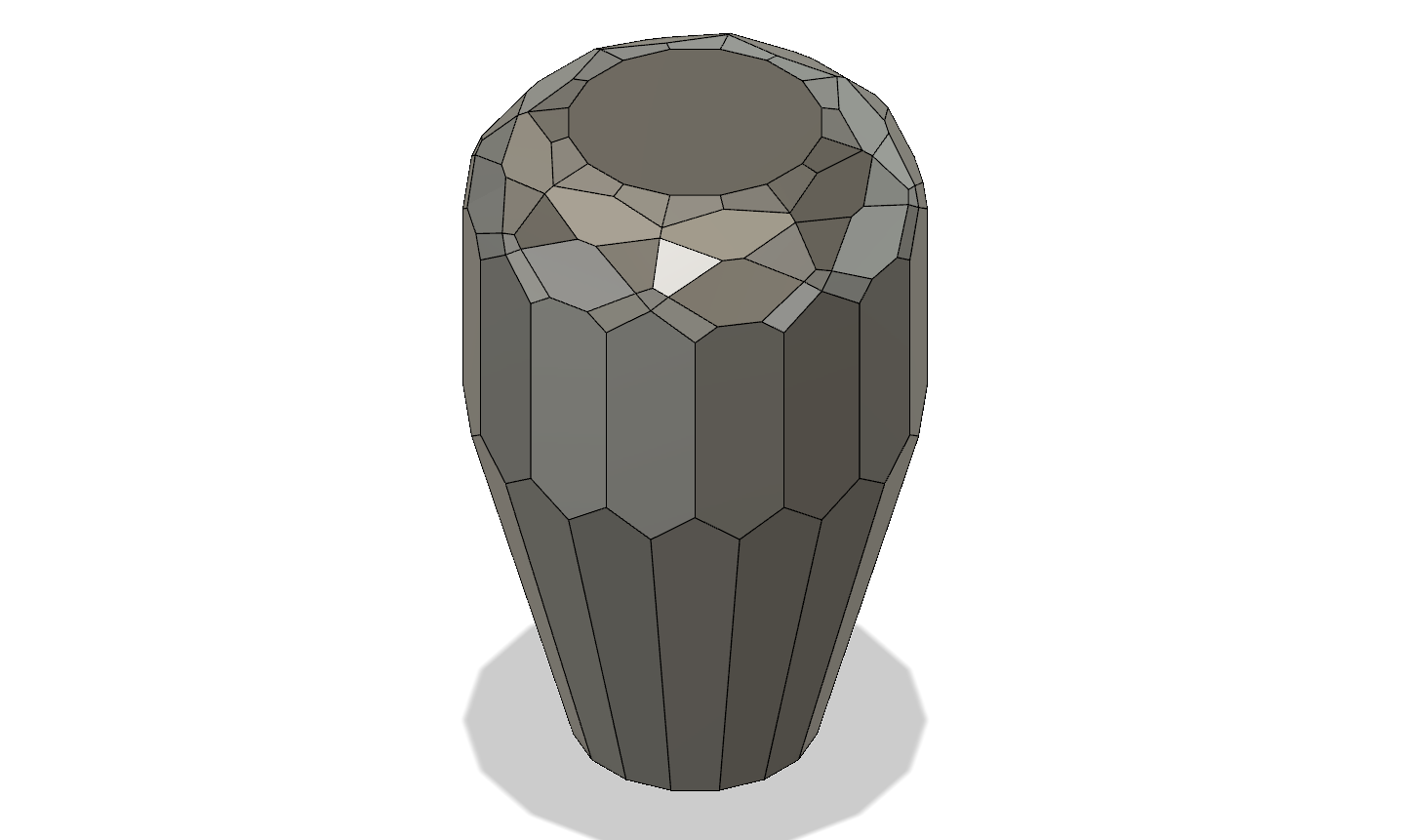
The body is a hexadecagonal prism. The bottom has a 16-sided taper. The top has a fillet divided into 5 tangent facets at 15 degree intervals. The 30 and 60 degree facets use a 16 instance circular pattern. The 15, 45, and 75 degree facets were patterned 8 times. This created a unique facet pattern on top which I like.
Prototype
Once I had enough of a design I printed it using colorFabb nGen on my heavily modified Ultimaker Original+ using a Micro-Swiss 0.8 mm diameter nozzle. I used a relatively small layer thickness for the nozzle diameter, at 0.08 mm. This combination of nozzle and layer thickness provided thick walls to make the print sturdy with relatively little infill while still having enough layer resolution to show how the individual facets will behave.
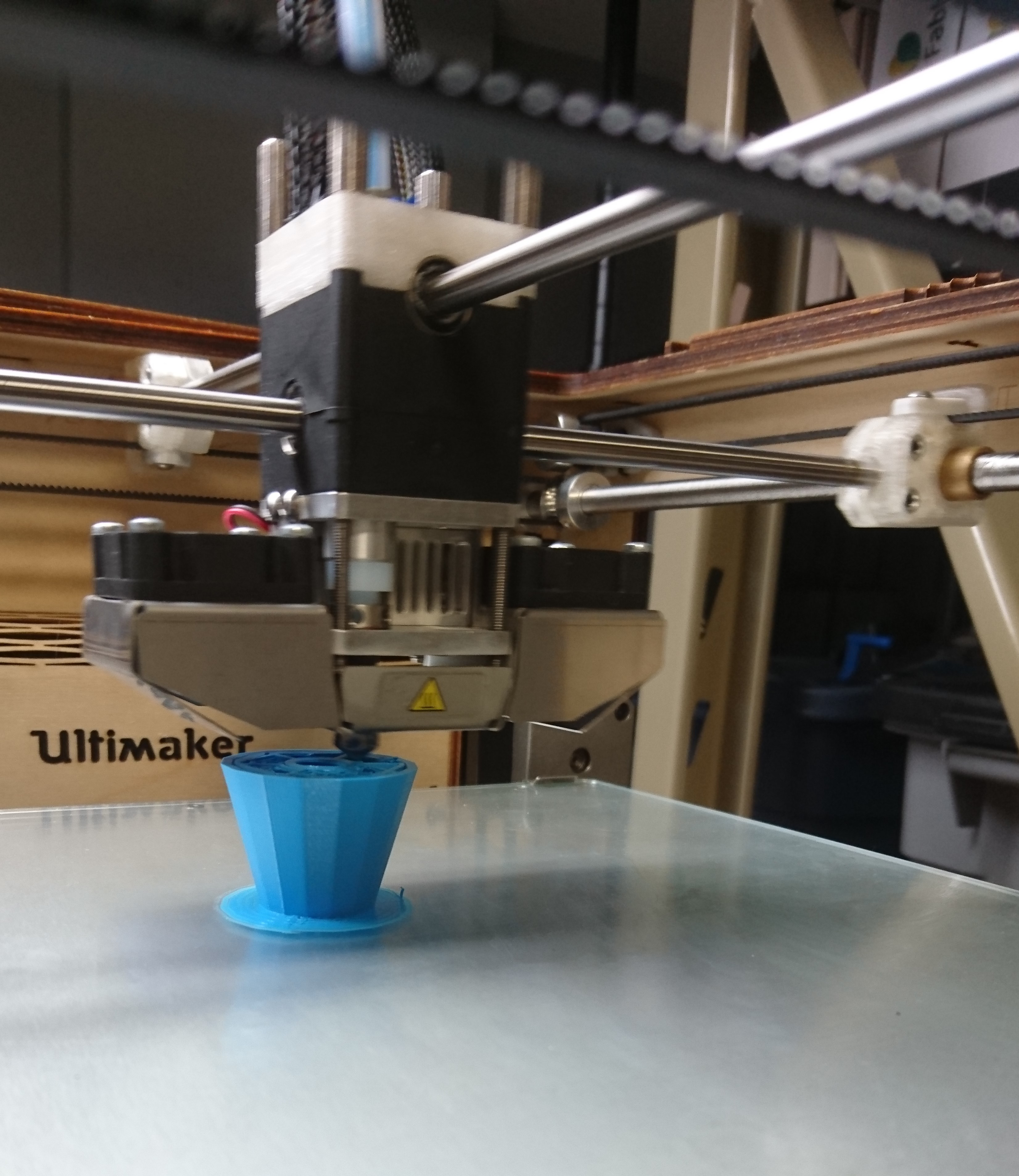
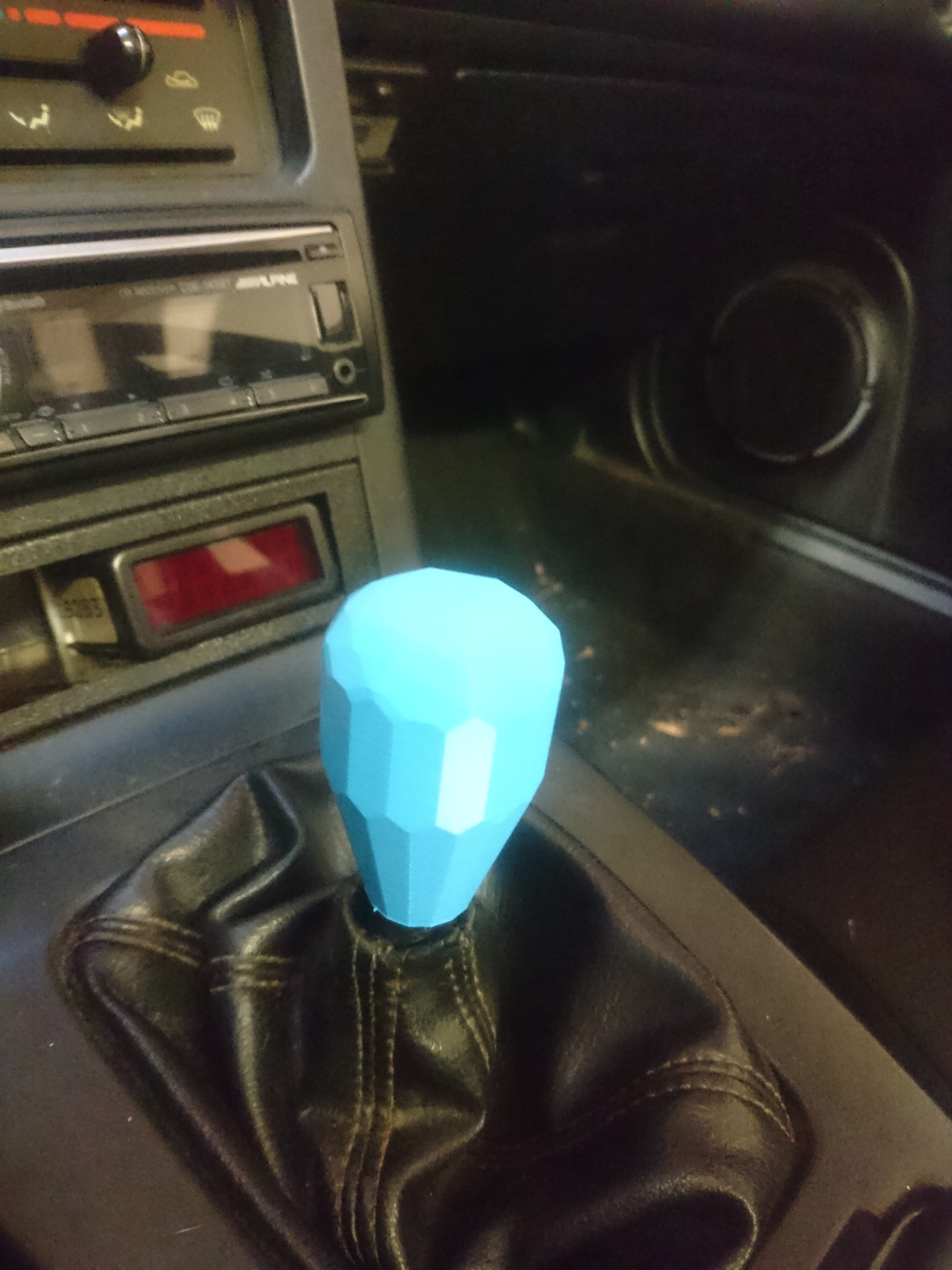
With the small layer thickness the print came out very well and produced interesting reflections. I’d modeled the threads with the expectation that I’d have to chase them with a tap. I was surprised to find that I didn’t have to and it threaded easily on the shift lever.
CAM
Once I was satisfied with the 3d printed prototype I started into some CAM in Fusion 360. I decided the part could be finished in two setups. The 16 sides of the body are finished along with one end. Then the part is flipped over and located accurately on those hexadecagonal faces to machine the other end. While it doesn’t necessarily matter which side is finished first, it made more sense to me to finish the top with the sides and then machine the tapered bottom second. The transition from the two setups would be easier to hide on the bottom of the part than the top.
I decided my first setup should have the coordinate system at the top of the model. I could then touch off of the part and do a facing operation until it cleaned up, thereby conserving material and allowing process development by moving Z0 into the part a short distance and repeating the program.
For the second setup I set Z0 to the underside of the part. Since that side of the part was finished in the previous setup, it made sense to have it be the datum for the second setup.
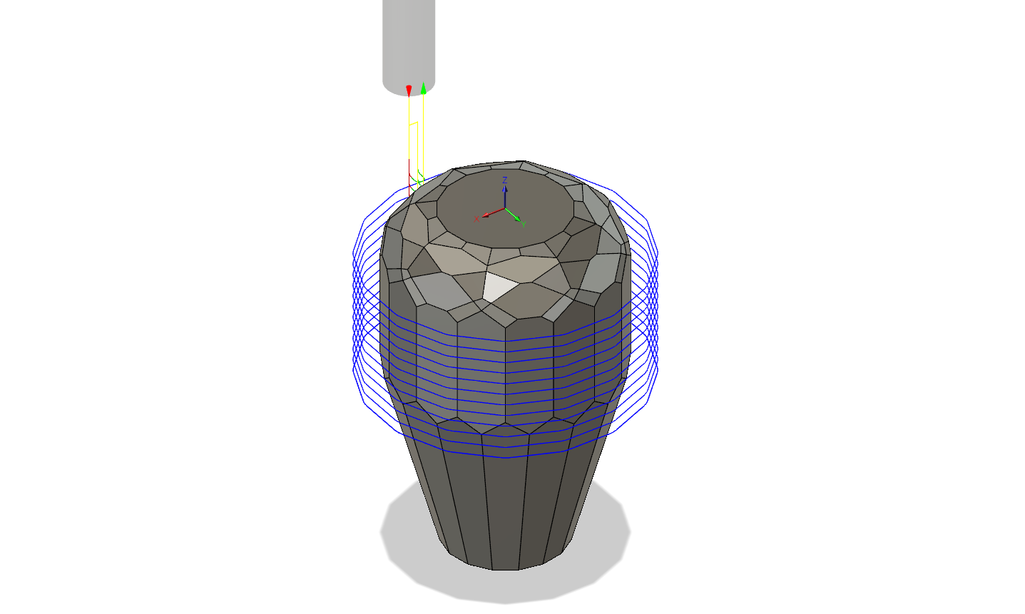
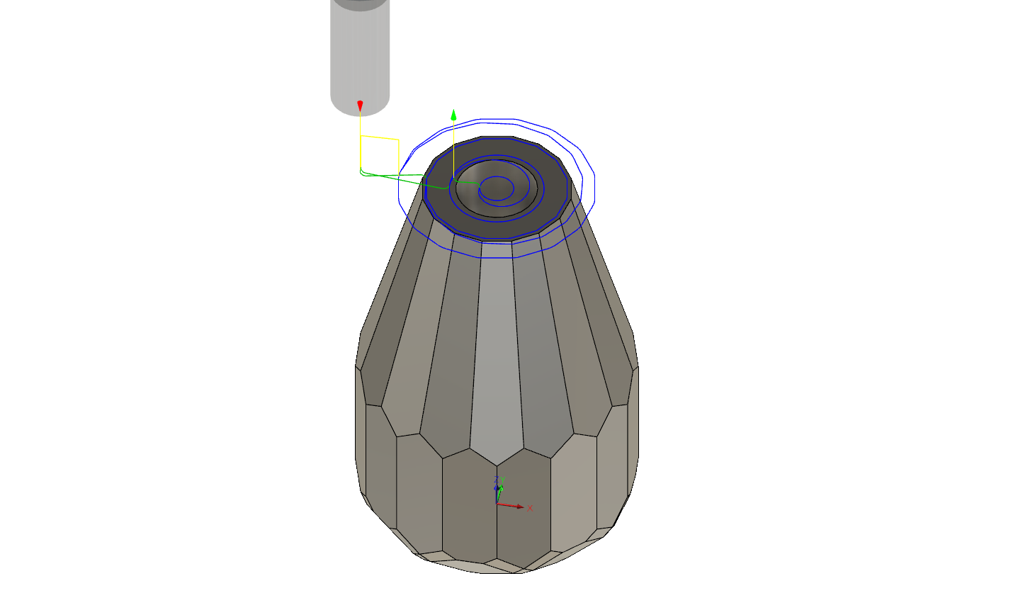
Roughing top
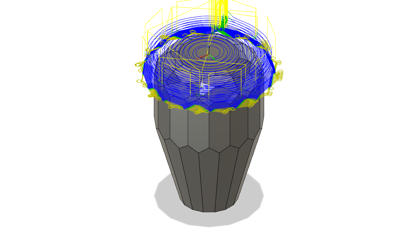
I used a 3D adaptive strategy for initial roughing and set my fine step down value to 0.2 mm in an attempt to leave a uniform amount of axial and radial stock for the finishing operation. I set my axial and radial stock to leave to 0.1 mm. This created a rather slow and inefficient roughing operation.
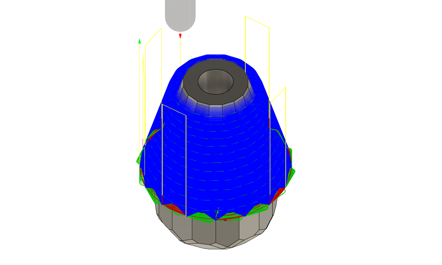
Roughing and finishing sides
I had trouble getting an acceptable surface finish for the sides. I think a larger diameter tool would have helped. What I eventually did was use two roughing paths at various depths, leaving a small amount of material and then doing a finishing pass and spring-back pass. It’s still not great, but it works.
This operation required the most stick out, so it defined tool stick out for the whole project. I set stick-out to have 2 mm of clearance between the top of the part and the tool holder in this operation.
Facing top
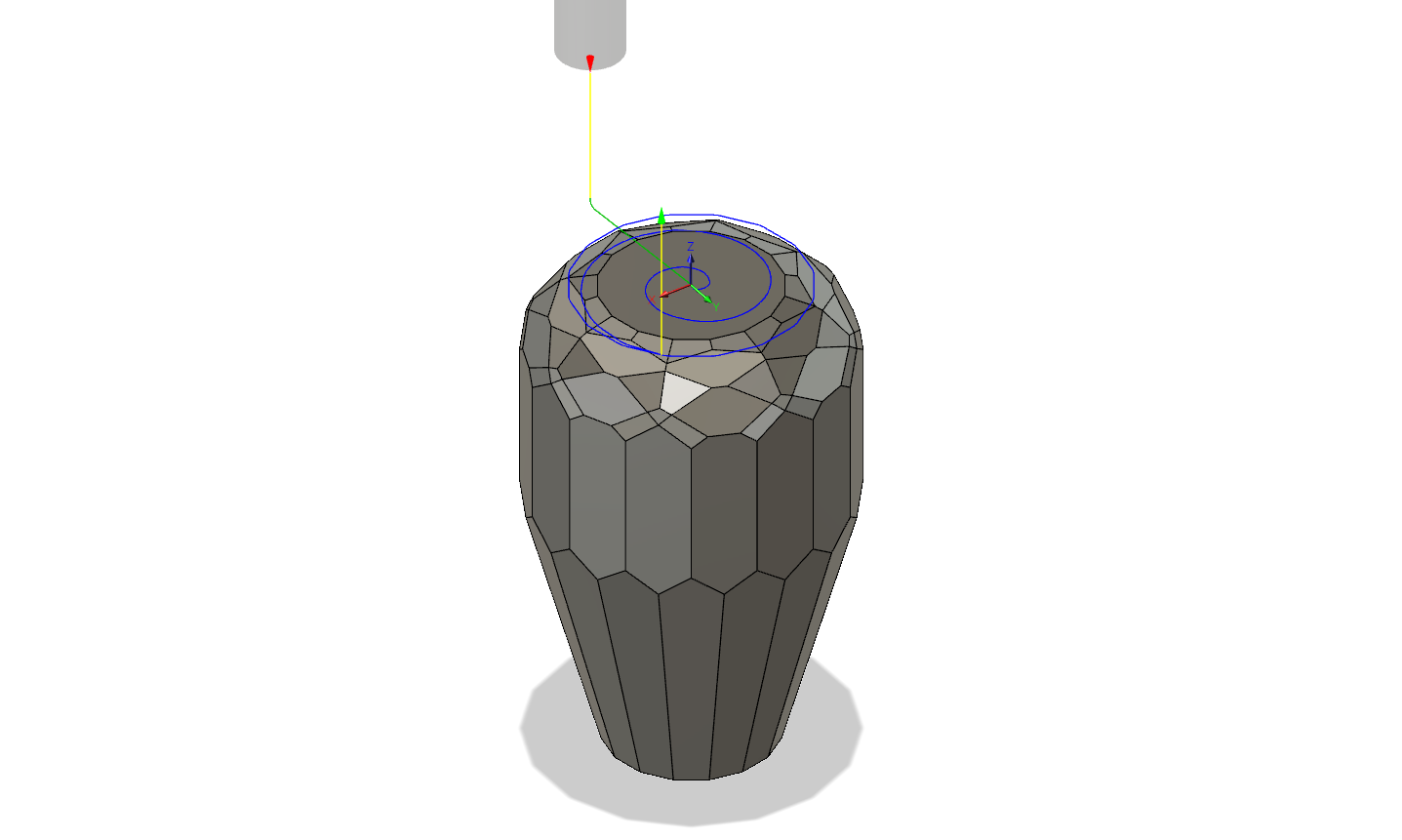
I think I’ll use a fly cutter to get a better finish if I have to do this operation again.
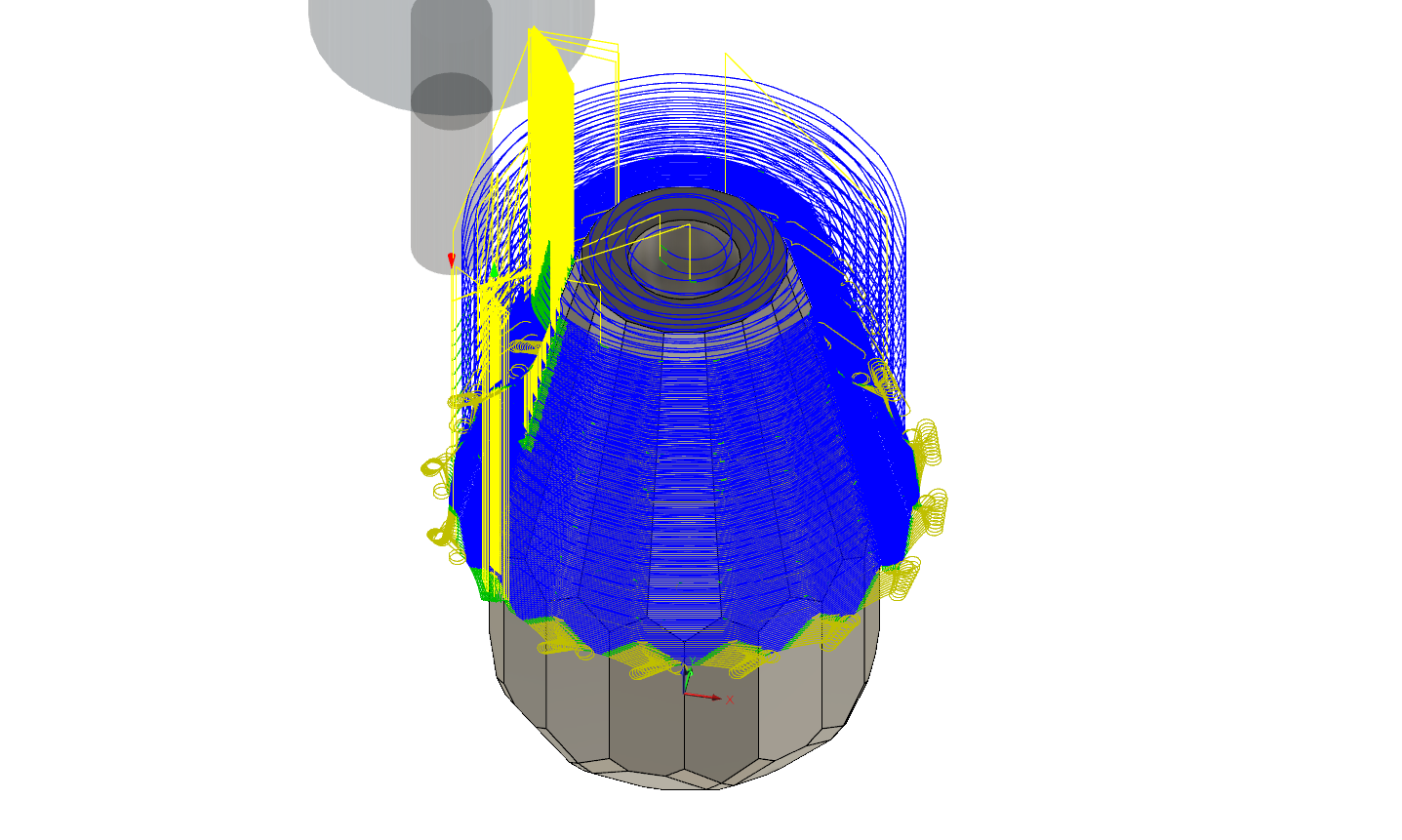
Finishing top
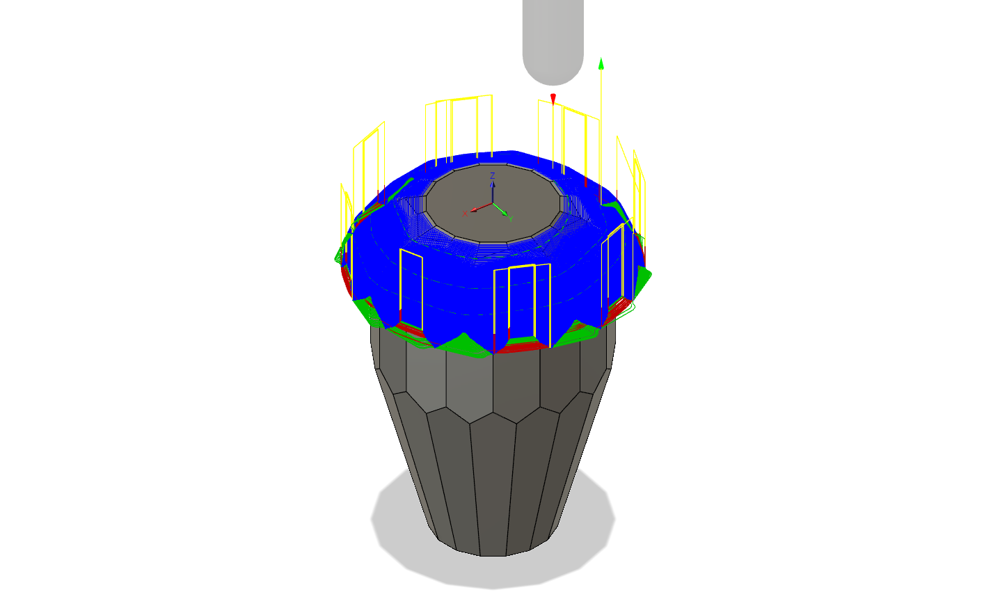
I spent a lot of worry about chip load, stock-to-leave, and step over for my finishing work. My surface finish is sufficient, but I’m far from optimized as my cycle time for this operation is almost an hour.
Roughing bottom
I used the same tool and parameters for top and bottom roughing.
Facing bottom
While I’d like to fly-cut the top, I think I’ll leave this one with the face mill, as it’s not visible.
Finishing bottom
 I used the same tool and parameters as finishing the top. I measured the required tool stick out on this operation and found that the minimal stick out to not be clamping on the flutes was sufficient to clear. This operation was longer than finishing the top as it has more surface area.
Tools
I was acquiring tooling for the Tormach while doing CAM and test machining of this part. I ended up using a Niagara C330M-080-D2-S.0-Z3 8 mm 3 flute AlTiN flat faced end mill for all roughing and for finishing the sides. I was unable to find a metric 3 flute long reach ball end mill delivered quickly, so I purchased a Melin EMG-1212-EB 9.525 mm 3 flute uncoated carbide ball end mill to use for finishing.
CNC
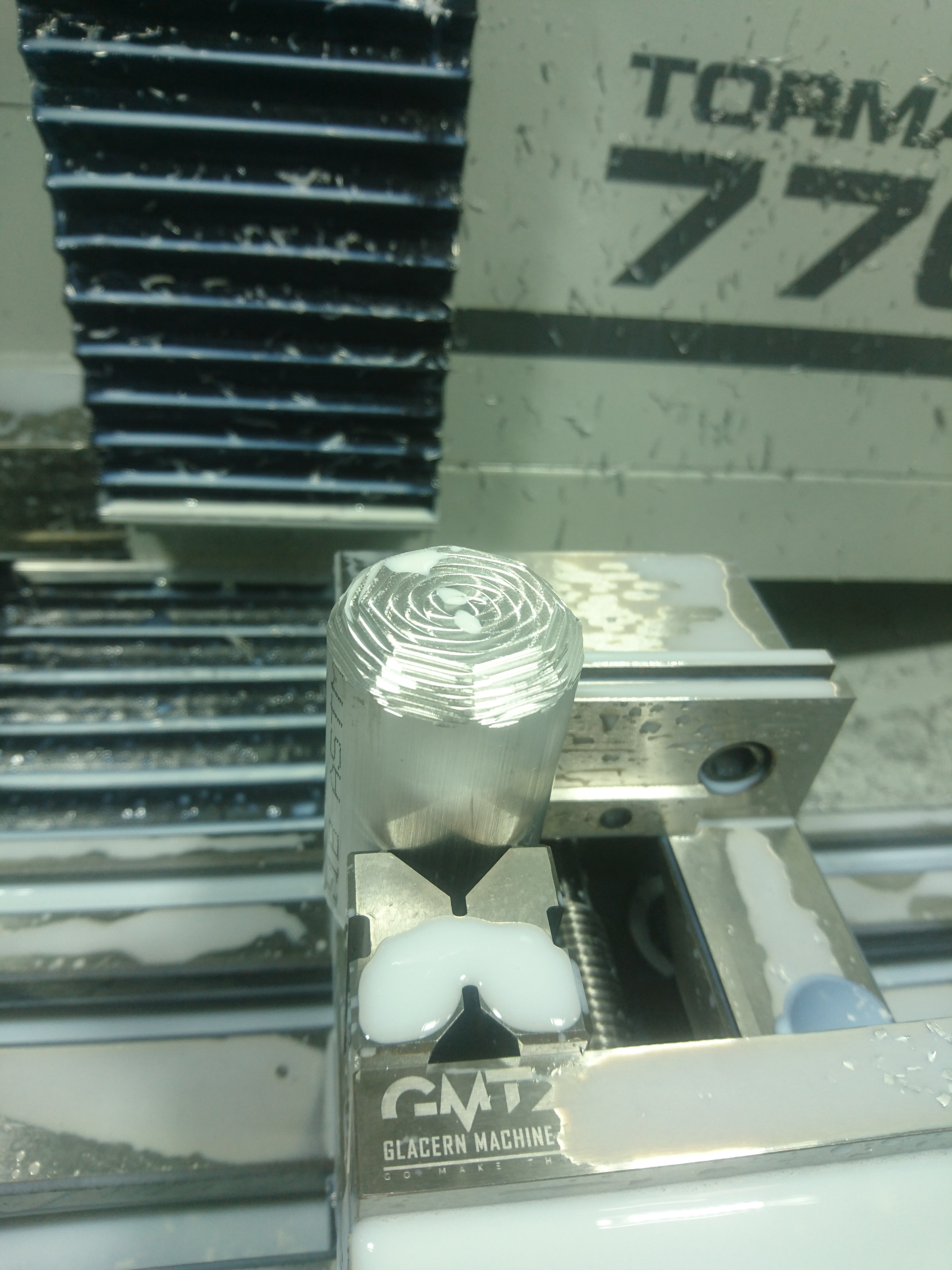
After printing I ordered some 6061 Aluminum rod to test with before machining the final part in brass. I cut a few 65 mm long sections of aluminum and one of brass. The part is 60 mm long overall, so that gives me some material for clean up and testing. I use a Haimer 3D Taster NG for locating parts. With this part I found the 0.01 mm resolution sufficient for matching the two setups.
I used a single vee block to hold the raw round bar in the first setup. For this setup I held the material with as minimal of stick out as required for finishing the sides without cutting into the vise jaws. This picture shows a test of the first roughing operation in Aluminum.
To do the second setup I found that setting a 20 mm Mazda BP wrist pin on the bed of the vise to put the part on top of was the right height to allow the taper to be finished without cutting into the jaws and kept the piece sufficiently square.
Final part
Once I was confident in my tools, setup, and programs I loaded up my brass piece and started cutting. A few hours later this emerged:
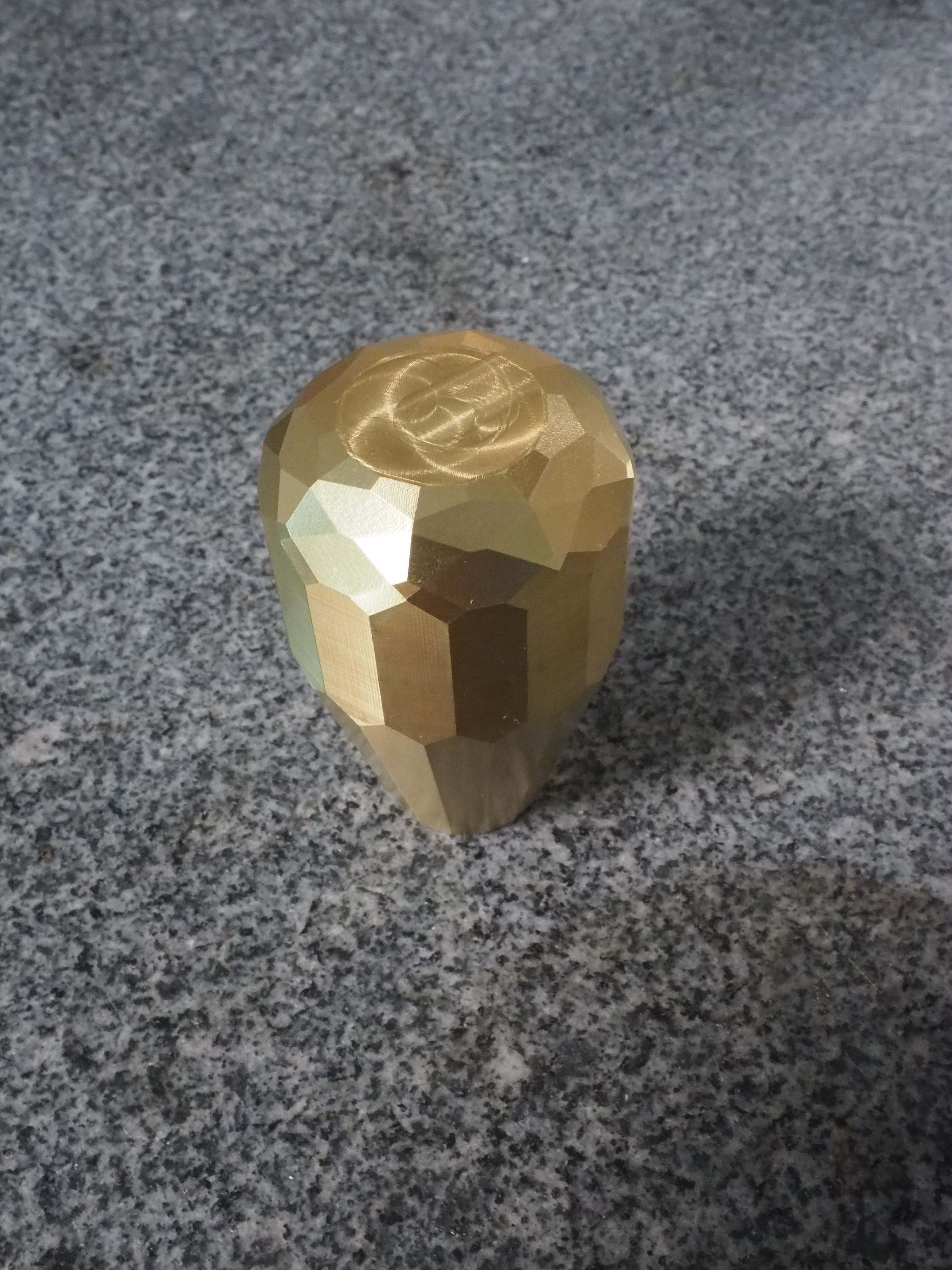
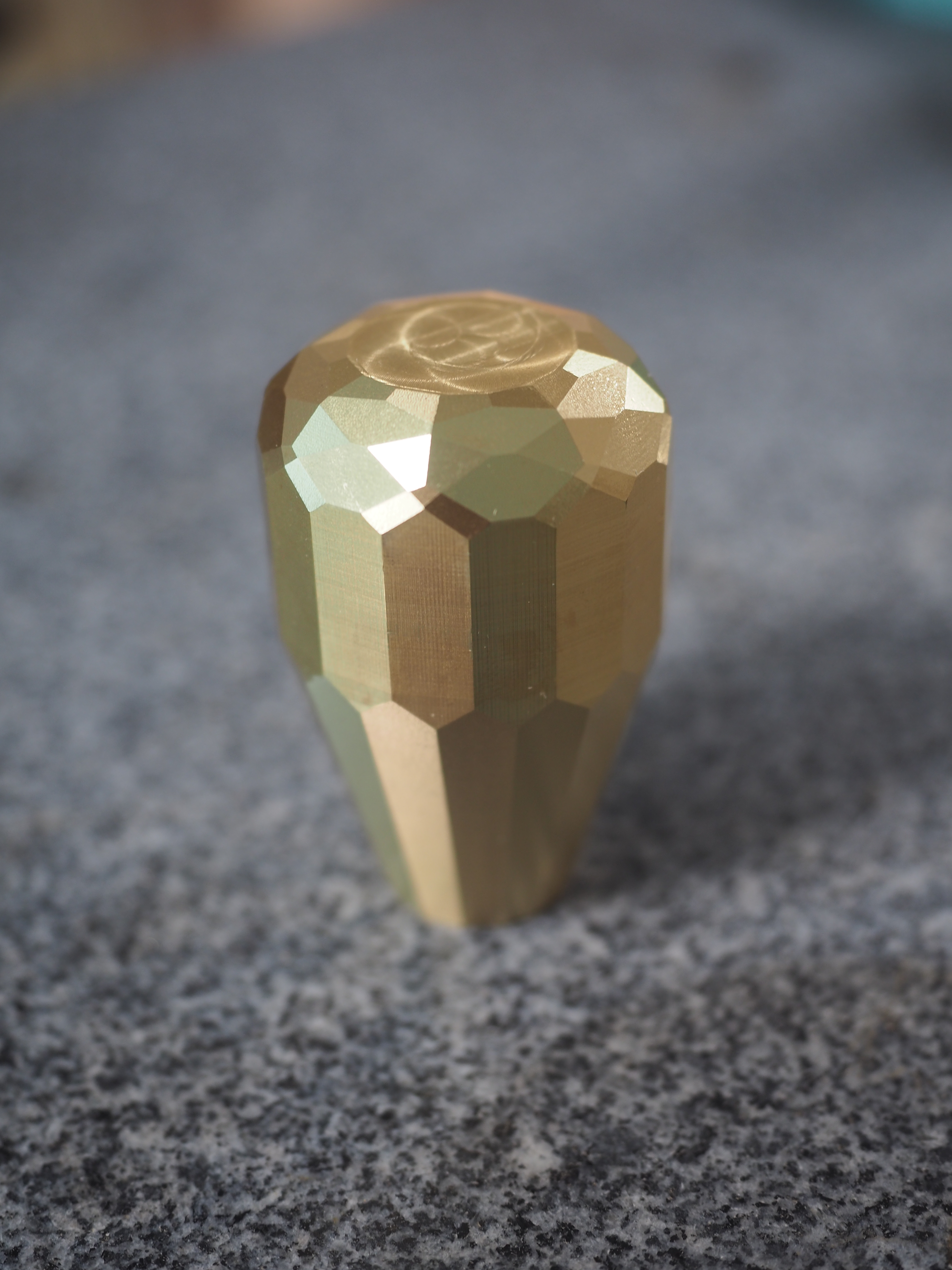
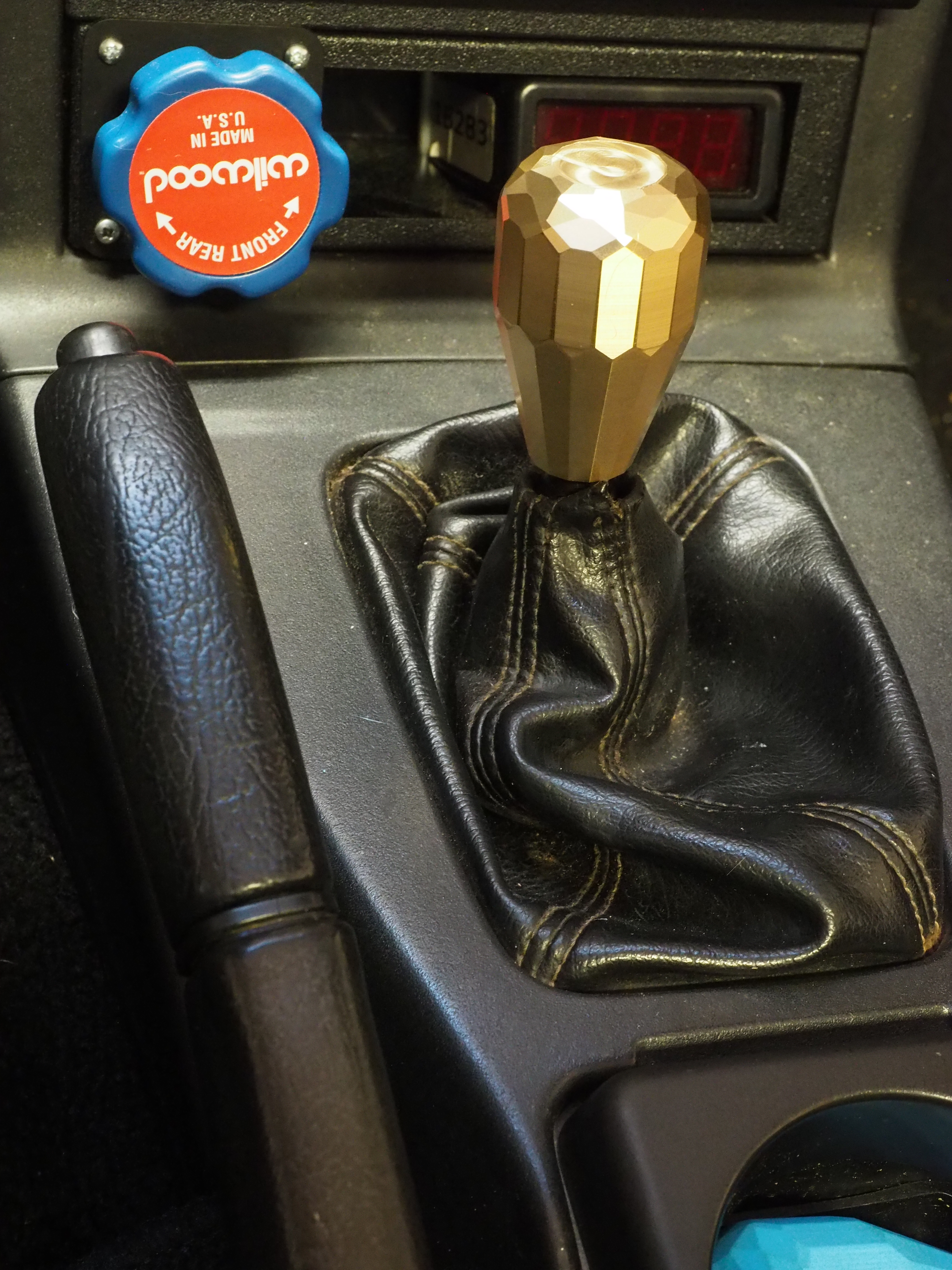
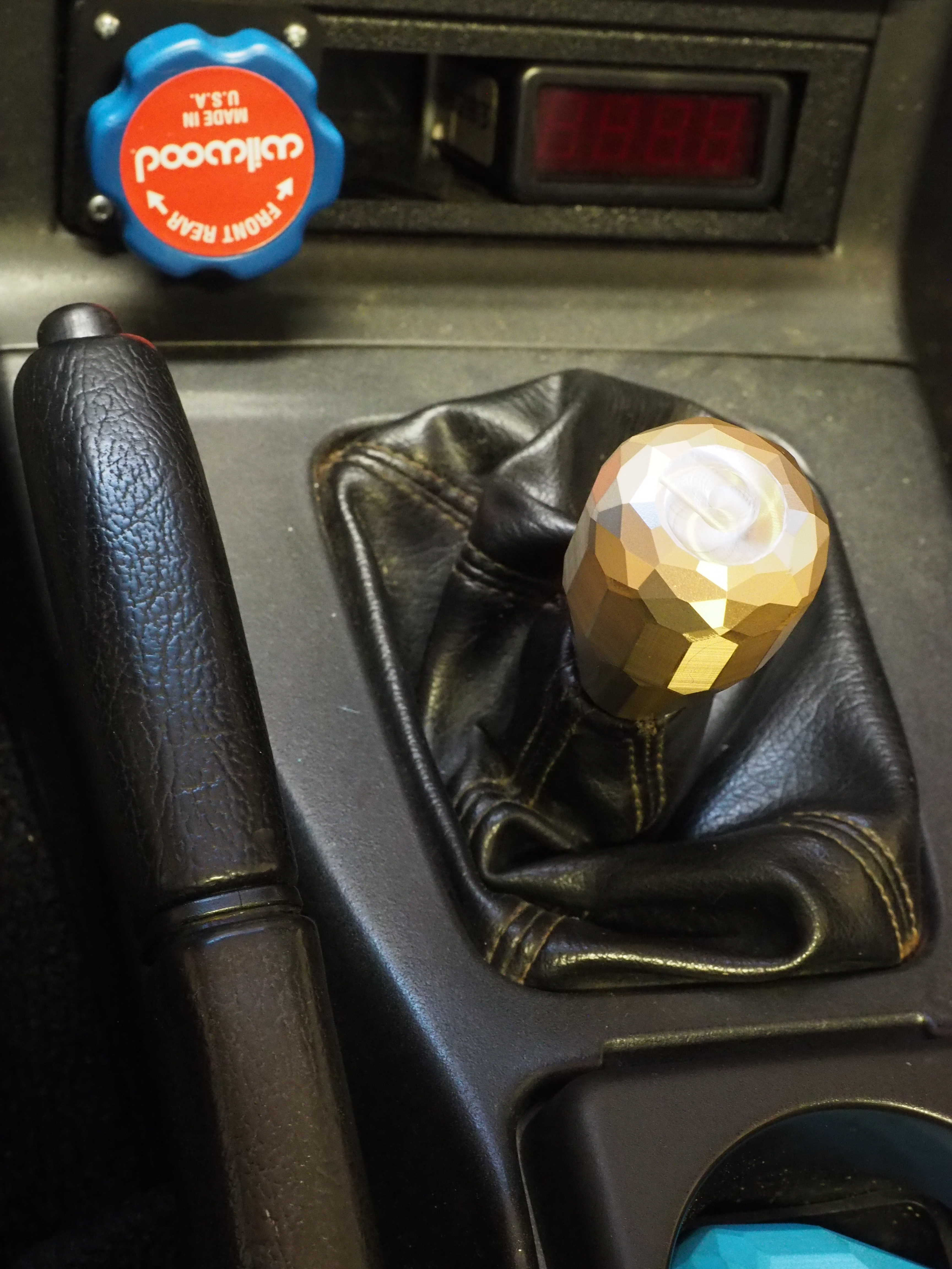
I think it looks and feels right at home in the Roadster’s interior.
Conclusion
This is the first part to come out of my Tormach. I am very pleased with the machine and am really looking forward to building out my tooling and working with it. Models, G-code, and further information is available in this gitlab repository.
While I was doing some CAM verification on the Aluminum prototypes I found a faceting that I thought looked better, but was having gouging on finishing. I think it was the exact wrong combination of facet size, ball nose radius, and angle. I think if I get a chance to do this again I’ll incorporate those facets and try cutting them with a much smaller ball.
I think the next thing I want to try is working with several parts in the machine and doing operations between the parts to reduce tool changes. I think it’d also be a good opportunity to work on some soft jaws or more advanced work holding.
Feel free to contact me if you have any questions or comments about this project.