Split cotters for the Quorn part 1
Introduction
The Quorn involves quite a few instances of clamping a shaft. Prof Chaddock shortly discusses a system of clamping called split cotters before suggesting that slitting the castings is the more appropriate solution. Hemingway Kits’ includes information on implementing split cotters. In this post I’m going to tackle the split cotter fixture and cotters themselves. And I’ll try not to mistakenly call them split collets.
About split cotters
Various methods of manufacturing split cotters are detailed on the internet. Many of them seem overly complicated to me. Luckily, Hemingway Kits construction manual closely follows a fellow Quorn builder, Tom. He has a great writeup on the design and construction of his split cotters, including a rather straightfoward and simple fixture.
Fixture
I drew up my fixture in Autodesk Fusion 360 from Hemingway Kits’ drawings.
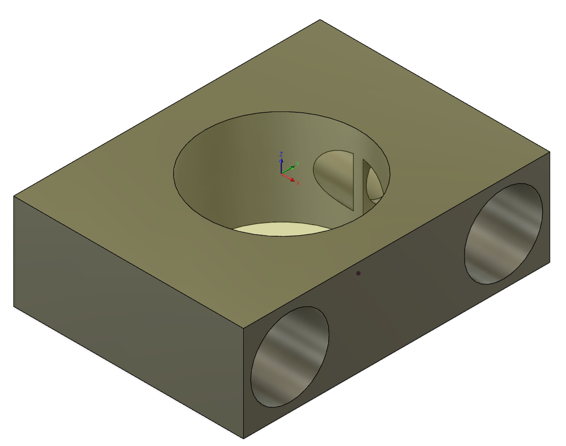
Other methods of manufacturing split cotters require the cotters to be through drilled for the minor diameter of the internal threads, then drilled half-way for the clearance diameter. The cotters are then machined for fitting to the shaft, then slit in half. I find this a bit painful compared to the elegant fixture method Hemingway suggests.
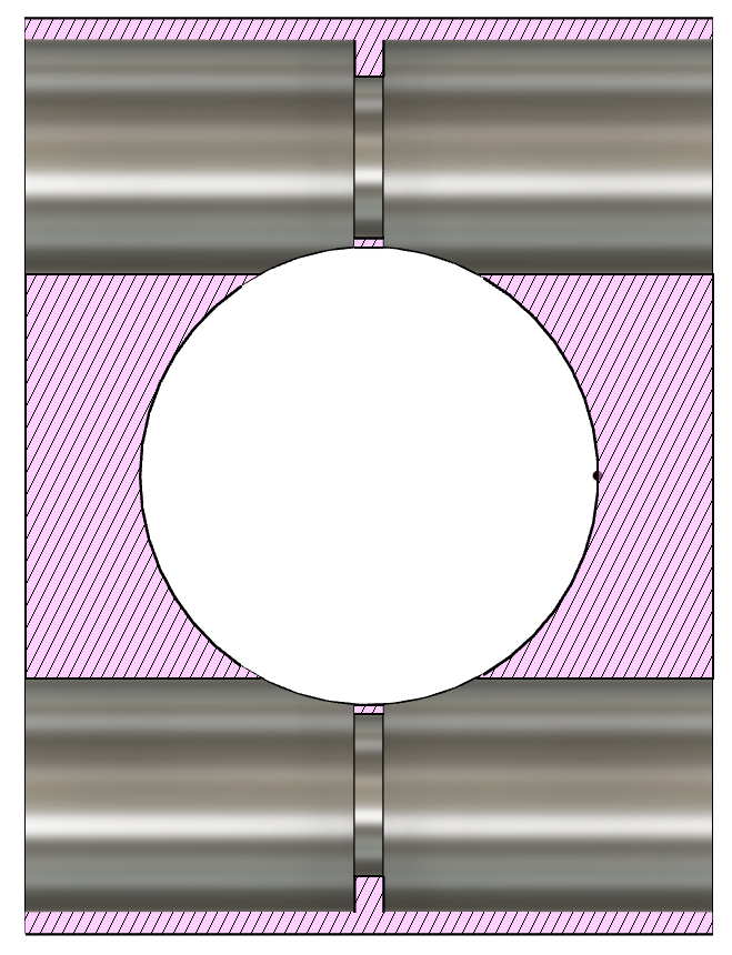
This fixture clamps either half of the cotters tightly on either side of the fixture.
Material
My split cotter fixture starts its life as a bar of 5/8 inch (15.875 mm) thick, 2 inch (50.8 mm) wide and 6 inch (152.4 mm) long low-carbon steel bar from McMaster-Carr. I chopped off 38 mm with an abrasive saw, did some quick face clean up on a stone, and dropped it into a Kurt DX6 on an ancient Haas VF4. I didn’t bother facing the block, as I’d be basing all of my work coordinate systems on the first feature I’d be putting in.
Shaft bore
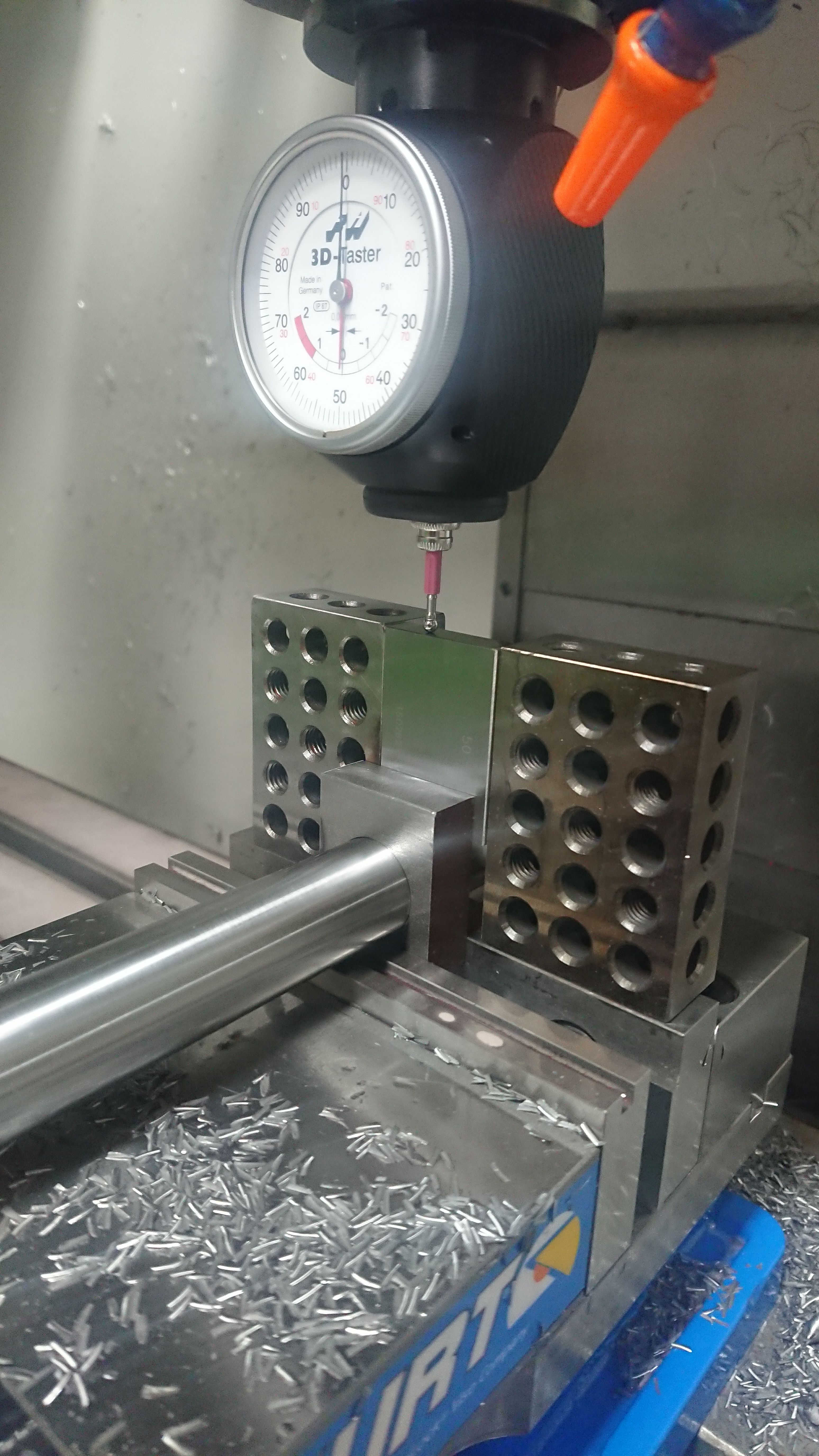
Because my first operation starts with a rough bar with mill finishes on four sides and saw finishes on the remaining two it made the best sense for me to center my coordinate system on my stock. I touched off of both faces in X to find the center there, both faces in Y to find center there. I then rechecked both to ensure the sides were sufficiently square. In this case, I felt the mill finish was sufficiently square for my purposes.
The first operation I did was to drill and pocket the fixture fo the 1 inch (25.4 mm) shaft. I through drilled using a 10.5 mm stub drill. I like to predrill pockets with a stub drill. They’re rigid, so they do not require a spot drill for this task. I choose a drill size large enough to clear my chosen end mills. In this case the end mill was 10 mm.
Fusion 360 has good morphed-spiral pocket clearing toolpaths and I use them often, even as a finishing toolpath for flat surfaces, as I like the surface finish it produces. For round pockets this toolpath produces an Archimedean spiral. In this case these toolpaths won’t show, as it’s a through-hole. Here I use it as a roughing toolpath as the morphed-spiral does a good job of keeping chip load from a predrill. After roughing I used Fusion’s bore toolpath, which is a helical toolpath using arcs. I’d previously used this toolpath for interpolating the horizontal bores of the base castings. I’m using a different cutter in this case and so had to step out my bores until I had a tight slip fit.
Cotter bores
To put the cotter bores in I decided to locate my coordinate system not on the fixture itself, but on a shaft placed in the shaft bore. In this way the bore of the cotter bore would be precisely located with respect to the shaft bore, rather than off of the mill finish or saw finish faces of the fixture. My method for doing so involved using a 50 mm gage block on either side of the shaft to establish the shaft center in X and then blocking in the gage block so that it sat square on top of the shaft to touch off for Z. The Y location was less critical, so I did not mind centering that on the fixture.
I predrilled and pocketed for the cotter bores, but this time used a 6.35 mm reduced-shank end mill for pocketing. These bores are not exceptionally deep. They do not require the reduced shank end mill, but I will be using a similar predrilling and pocketing for the cotter bores on the base castings and those are rather deep for their diameter.
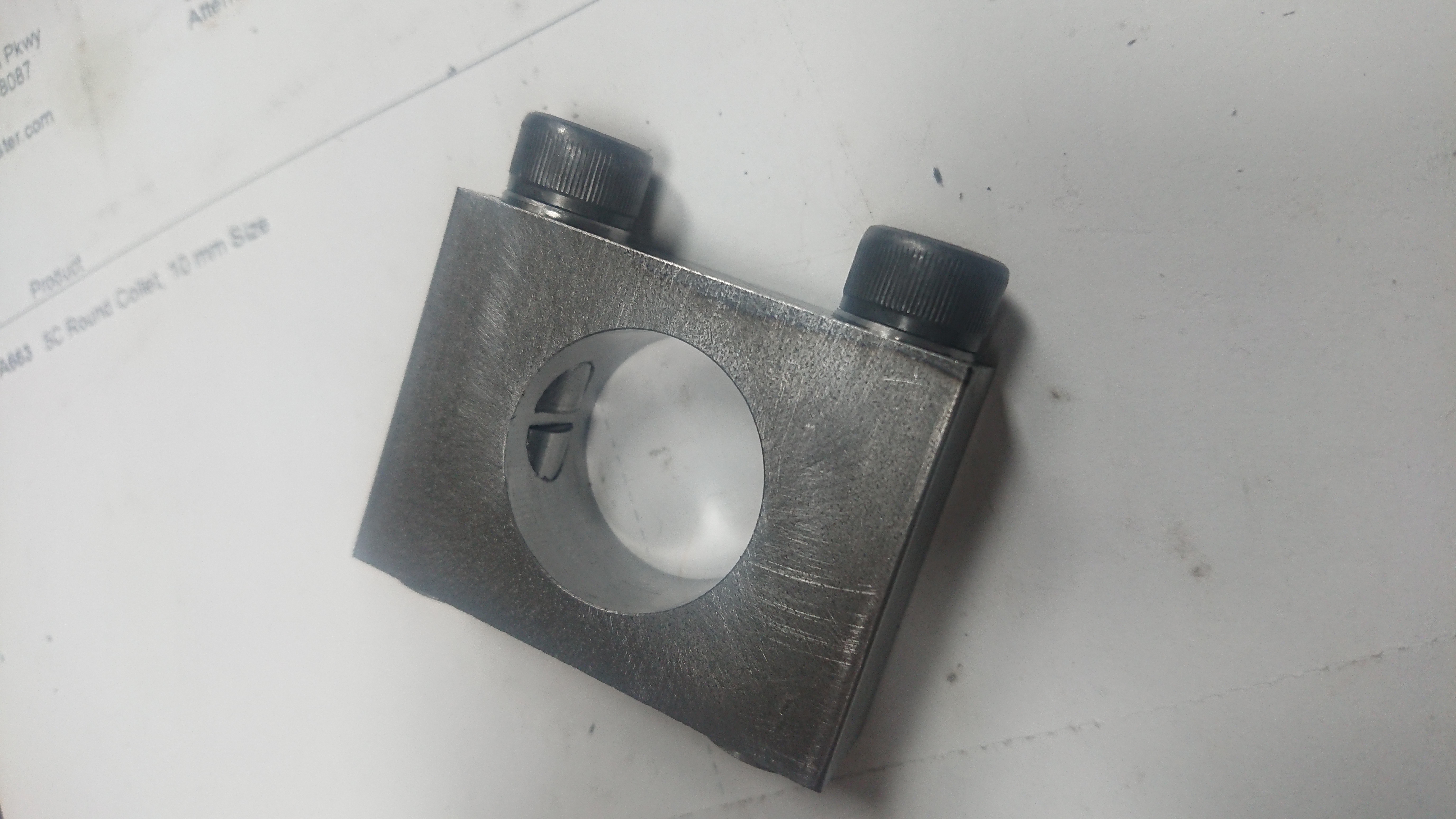
I flipped the fixture over and repeated the same process on the other side. After some filing, and clean up I set the fixture back up for the sake of finishing the cotters.
Cotters
My cotters started life as 300 mm of 13 mm diameter tight-tolerance 12L14 carbon steel rod. I dropped them into a 3 jaw chuck on a lathe at the local makerspace and fished a parting tool and tool holder out of the drawer. I through drilled and parted off the bar until I was through it. I considered tapping on the lathe, but instead held the necessary pieces in an ER32 collet chuck and held the chuck on a bench vise to tap. This worked surprisingly well.
After some deburring I dropped two sets of these at a time in my fixture and ran a boring toolpath to finish them. This operation went rather quickly!
Conclusion
I have two more sizes of cotters to make, but haven’t gone through the construction notes or drawings to find out exactly how many I need. I have 10 mm diameter of 12L14 for the smaller ones and expect I’ll need to order more material for more of the larger ones.
The next operation I intend to tackle is the cotter bores in the base castings.