Split Cotters for the Quorn part 2
Introduction
Having manufactured a fixture for the production of split cotters, and having manufactured the split cotters it was now time to drill and mill the hole in the right side base casting for its cotter.
Work holding
I’d like to think if I were in my own shop with my own machines I would manufacture some fun soft jaw fixture for holding this casting and that it would be elegant and robust and worthy of its own praises. For the time being I get to maintain that delusion because I’m not in my own shop and I’m not using my own machines. As such I cobbled together the workholding shown below.
I think I’m going to start a “Shameful Setups” support group.
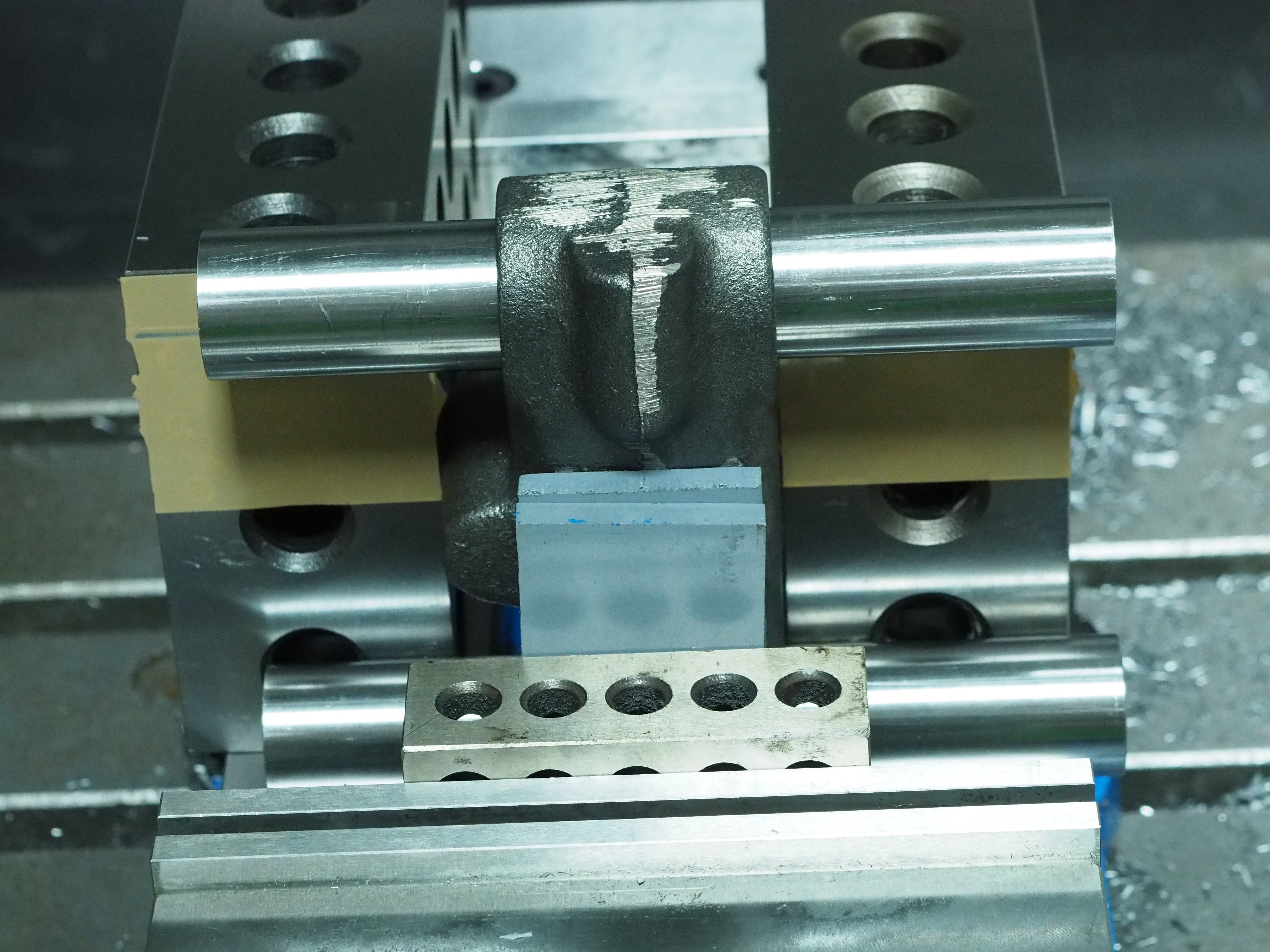
With the two horizontal shaft bores finished, it seemed appropriate to use these to locate the casting vertically. In this setup the casting is hanging between the sides of the bed of the vise. The bottom bar is sitting on the vise bed. Both bars are pushed up against a pair of 2-4-6 blocks which are sitting against the fixed jaw of the vise. The 1-2-3 block on the front jaw is to offset the front jaw from the casting, otherwise there’s a feature of the front jaw which would interfere with the casting since it sits below the vise bed. The PVC sheet allows for some compliance with the face of the casting.
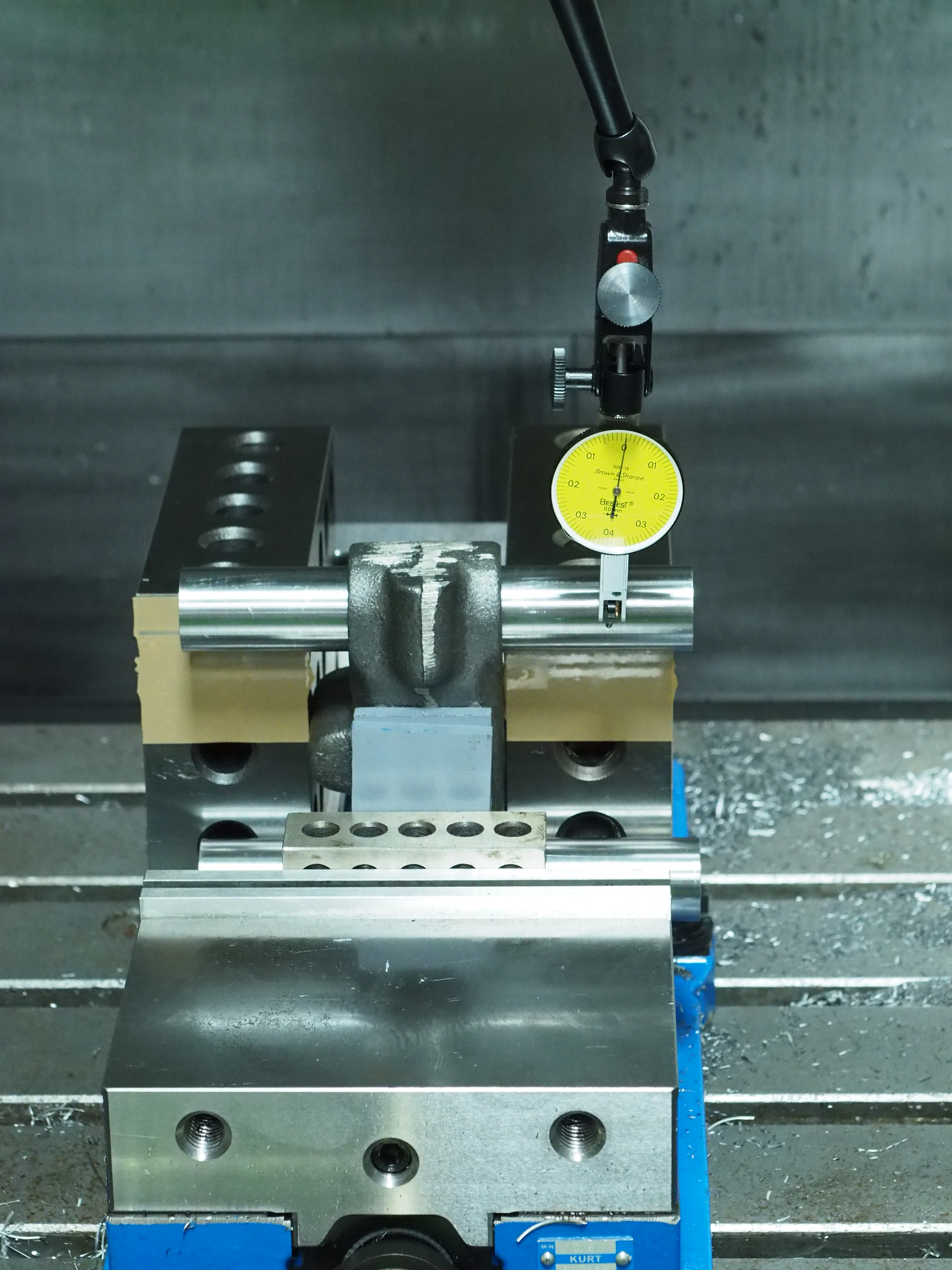
After devising this insanity I decided it’d be a good idea to check it, so I ran an indicator up the bars on both sides. I was surprised to find that they’re sitting square left-to-right, so the bars are in line with the X axis, but they were not square along the Z axis. The top bar was about 0.05 mm further back in the Y axis than the bottom bar.
I tried flipping over and turning around the 2-4-6 blocks and got the same results, so I pulled the blocks out and applied some packing tape to the front face of the blocks. While the tape is slightly thicker than I needed, it also compresses a bit. This brought me much closer to square top-to-bottom.
Coordinate system
Similar to the machining operations for making my cotter fixture, I based my coordinate system off the top of the top horizontal shaft. This ensures the relationship between the cotter bore and the shaft bore is as intended. To establish this, and similar to my cotter fixture I established the center of the top bar by touching a Haimer 3D Taster off of a gage block set up against the top bar. This provides a full plane for the taster to touch off of.
Operations
With the part set up and the coordinate system established it was time for cutting operations. Here we go!
Drilling
For pocketing operations I like to start with predrilling. This pocketing was done with a 6.35 mm end mill, so predrilling was done with a 6.8 mm stub flute drill. Predrilling with a stub flute drill removes the need for using a spot drill in this context. Because the Haas does not have a very good coolant system I elected to do full-retract peck drilling.
This operation is a good chance to look at the G-Code that Autodesk Fusion 360 posts for the Haas.
%
O01001 (cotter bore)
(Using high feed G1 F5000. instead of G0.)
(T8 D=6.8 CR=0. TAPER=118deg - ZMIN=-26.19 - drill)

N10 G90 G94 G17
N15 G21
N20 G53 G0 Z0.

(Drill1)
N25 T8 M6
N30 S1170 M3
N35 G54
N40 M8
N45 G0 X0. Y-17.2
N50 G43 Z21.858 H8
N55 G0 Z11.858
N60 G98 G83 X0. Y-17.2 Z-26.19 R8.986 Q1.7 F163.84
N65 G80
N70 G0 Z21.858

N75 M5
N80 M9
N85 G53 G0 Z0.
N90 X-6.35
N95 G53 G0 Y0.
N100 M30

%
There’s something to be learned here. First, the machine this runs on is old enough to drink. So programs are given numbers, not names, and this one thinks its program O01001.
Second, the post lies. It says it uses G1 F5000 instead of G0 for rapid moves, but the program has G0s in it. This program includes line numbers, even though the machine doesn’t require it. It can be useful for debugging, as the machine will display the problematic line without saying what line it is in the program. Including these numbers in the program can help.
Next, this post puts out a G94. This Haas doesn’t like that. I don’t know what it was supposed to be. Whenever I post for this machine I have to remove that. I’ve considered digging into the post-processor but I don’t intend to do much more with this machine.
Most of the rest of the program is straight forward, but what keeps it a compact enough program is that it uses a canned cycle for the drilling itself. This is shown on line N60. I think its really cool when a CAM package and post-processor make use of a canned cycles, especially on these old machines.
Pocketing
After predrilling I did pocketing using a 6.35 mm reduced-shank end mill. I picked up a pair of these end mills specifically for this operation, as the resulting pocket is 13 mm in diameter and over 30 mm deep. Using a reduced shank end mill allows me to have maximum rigidity for whatever minimum stick out I need. I left 0.1 mm of radial stock for cleanup using a boring operation.
Aftermath
After finishing these pockets I was excited to put a shaft in and see how well the cotters work. I did so, to find that the cotters and cotter bores did not line up correctly. The good news was that the casting was machined correctly. The bad news was that I needed to make a new cotter fixture and remachine my cotters.
So next I’m going to be doing exactly that. Let’s do the time warp again.