MAP sensor calibration
Introduction
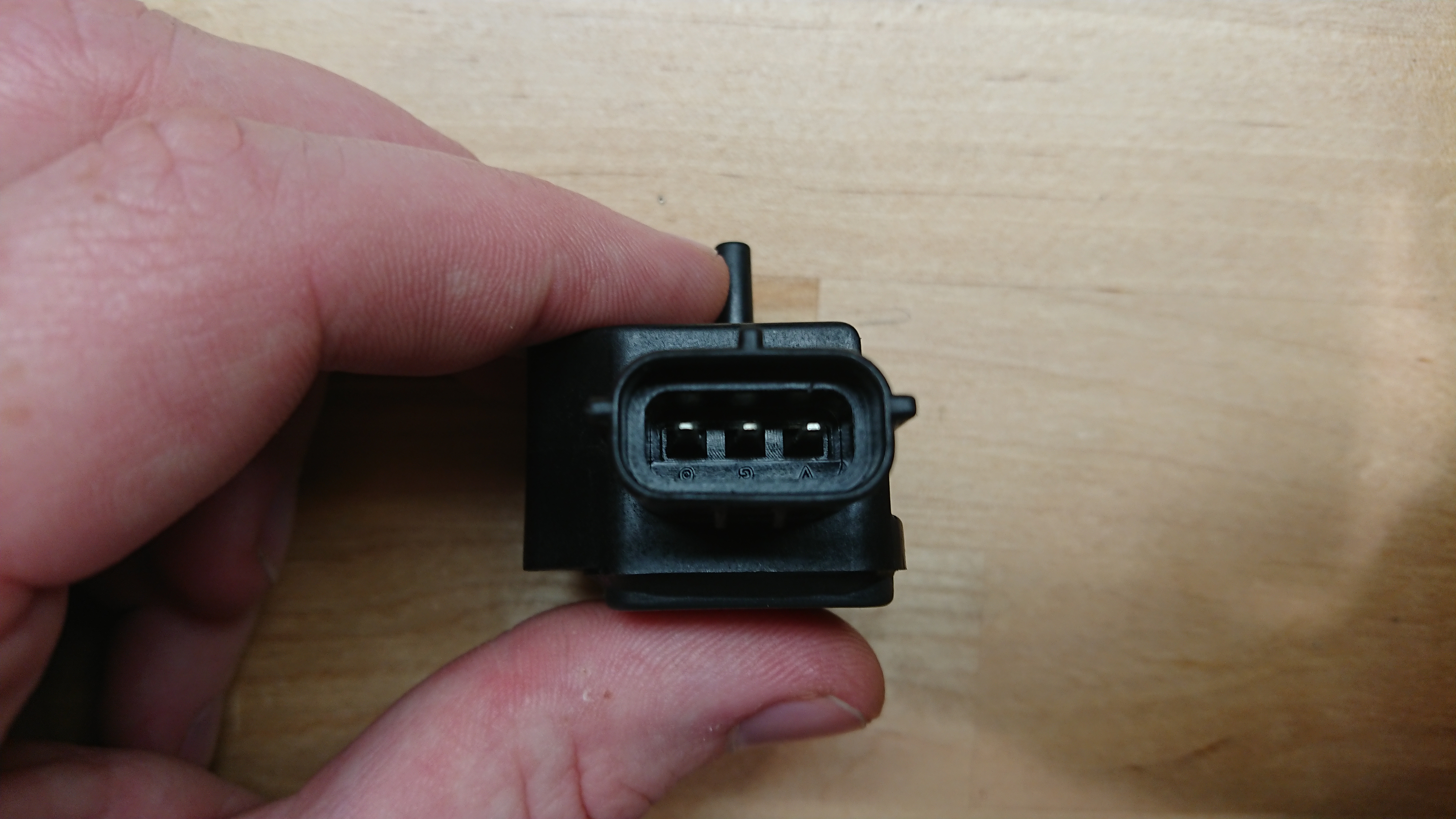
The Suzuki EA11R has an air pressure sensor mounted on the firewall. It is connected to the intake manifold to measure manifold pressure. This manifold air pressure (MAP) sensor is used by the engine management system to determine fuel metering and spark advanced. This article describes an experiment to determine the relationship of inputs and outputs of this specific sensor.
Sensors
This sensor, like most MAP sensors, has three connections with the engine management system. The engine managment system provides 5 V of DC power to the sensor and provides a calibrated ground return. It then outputs a voltage on a third pin which is proportional to the manifold pressure.
That output voltage is read by an analog to digital converter (ADC) on the engine management system. The relationship between manifold pressure and voltage output is different for different sensors.
Experiment
Electronics
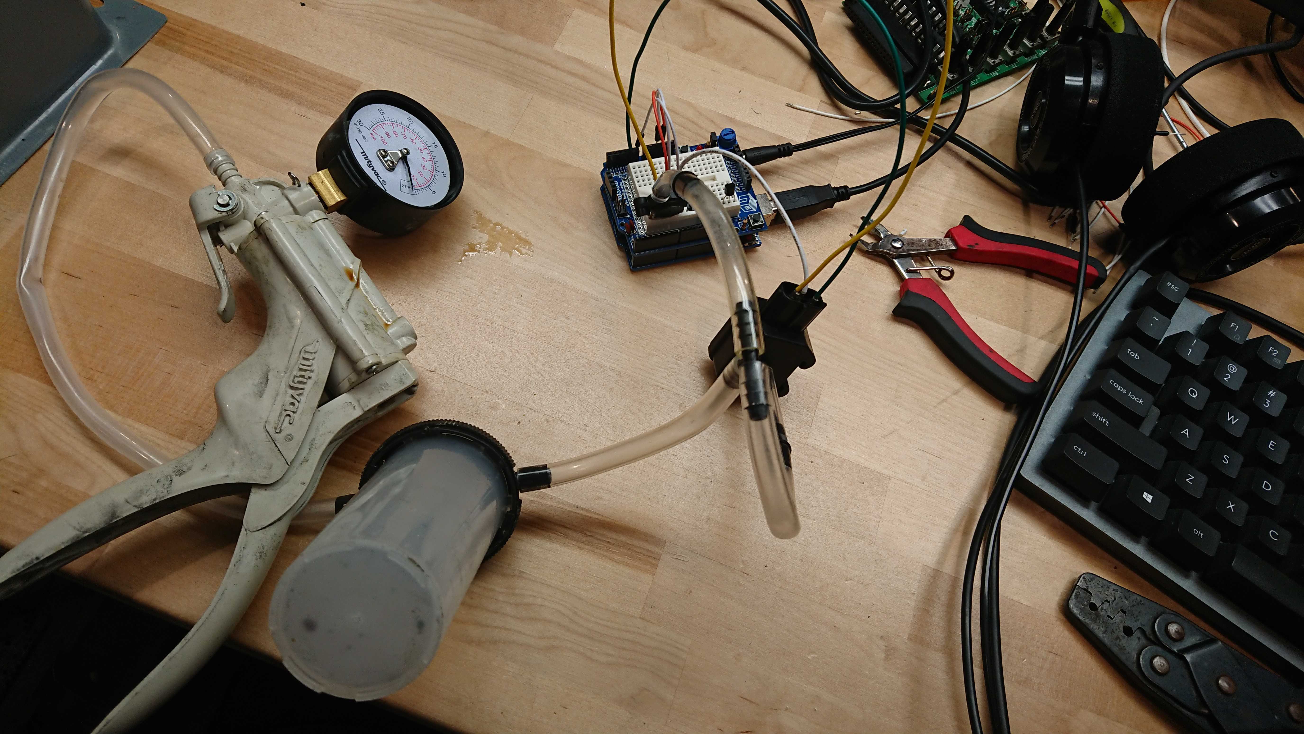
To determine the pressure to voltage relationship of this sensor it was compared to a sensor with a known transfer function. For this test the ubiquitous NXP MPX4250 was used for comparison. Both sensors are connected to a common pressure source and their outputs are recorded.
For this test both sensors were connected to an Arduino UNO. The Aruino provided 5V to the sensor and a common ground. This ensures accuracy for the ADC. A short program was written for the Arduino which took readings from the two ADCs and wrote them to the serial output. A delay reduces redundant values.
Pneumatics
A vacuum pump was connected to an accumulator and then to the two MAP sensors. This provides a common and consistent vacuum source for both sensors.
Procedure
With the input and output relationship of these sensors being linear, the entire range of the sensors output is not necessary to determine the transfer function of the new sensor. A vacuum was applied until he pressure would not go any lower. The system was then allowed to leak vacuum until it returned to atmospheric pressure while outputs were recorded.
Results
MAP sensor transfer functions
Most engine management systems use a table with a series of two points to calculate MAP. In some cases this requires a value at 0 volts and 5 volts. Sensors like the MXP4250 have transfer functions which don’t ever intersect 0 V or 5 V. In these cases the slope of the output is extrapolated to 0 V and 5 V.
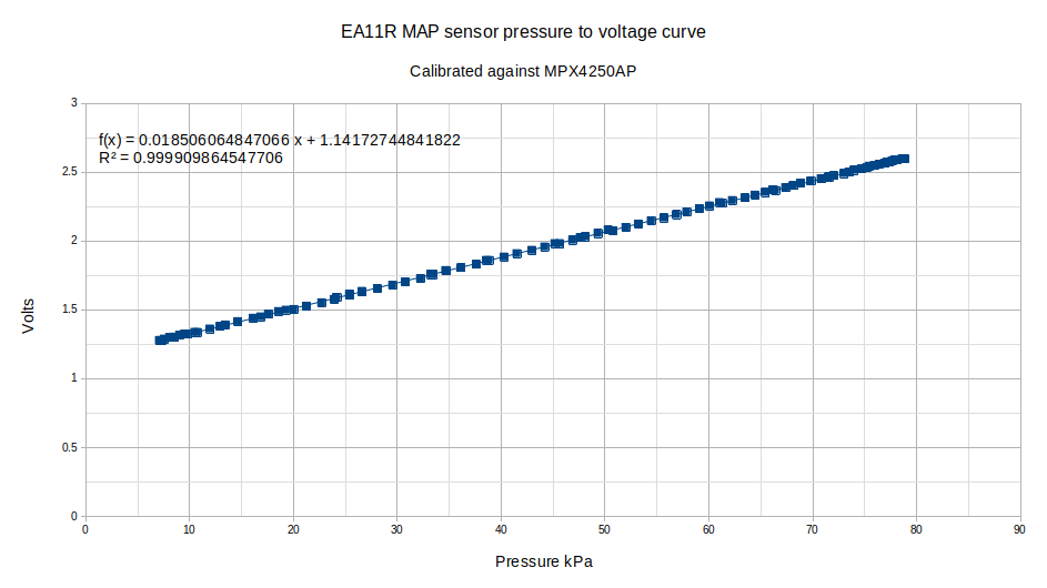
![]()
The Arduino writes ADC count. The UNO has a 10 bit ADC. This means that a 0 V input is represented with 0 and a 5 V input is represented as 1023. The first step in processing the results was to take the output data from the MXP4250 and convert its ADC counts to voltage. This voltage was then converted to pressure from the transfer function on the MXP4250’s datasheet. The Suzuki MAP sensor’s ADC was then converted to voltage. A linear fit was then made with the pressure values from the MPX41250 and the Suzuki MAP sensor’s voltage.
Conclusion
If this sensor reads all the way to 5 V, which is unlikely, then it tops out at around 208 kPa, meaning that the ECU in the Cappuccino can’t read boost over about 1.1 BAR of boost. The OEM turbocharger allowed for 0.8 BAR of boost.
Suzuki released ECUs for the EA11R which allow for larger turbos and higher boost, Up to 1.3 BAR. With the MAP sensor only reading to 1.1 BAR, the fuel and ignition tables top out at 1.1 BAR.