Scanning, engineering, and printing a downpipe
Introduction
Here a workflow is presented for developing and test fitting a replacement downpipe for the Suzuki Cappuccino using flat bad scanning, a portable measuring arm, AutoDesk Fusion 360, and an Ultimaker 3X 3D printer.
The part
The Suzuki Cappuccino uses a large catalytic converter located in the down pipe directly off of the turbocharger. The part uses cast iron construction and on many cars are a restriction to exhaust flow, limiting performance. For this project we’re developing a replacement part with the intention to perform better.

Measuring
The replacement downpipe needs to mate to the turbocharger and the rest of the exhaust system and fit within the bounds of the OEM downpipe.
To engineer a new part the old part must be measured. Two methods of measurement were implemented in this project. First the mating surfaces and gaskets of the part were scanned on a flat bed scanner. Second, the entire part was scanned using a Hexagon Absolute Arm.
Flat bed scanning
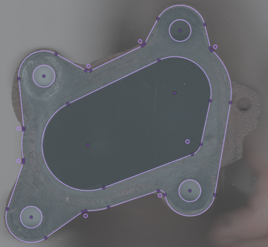
The reverse engineering process started with scanning the mating flanges on a flat bed image scanner with a pair of machinists’ scales. these images were brought into AutoDesk Fusion 360 and scaled so that the distances on the scales are correct. Measurements could then be taken from the scans and modeled so that geometric features can be created in a sketch.
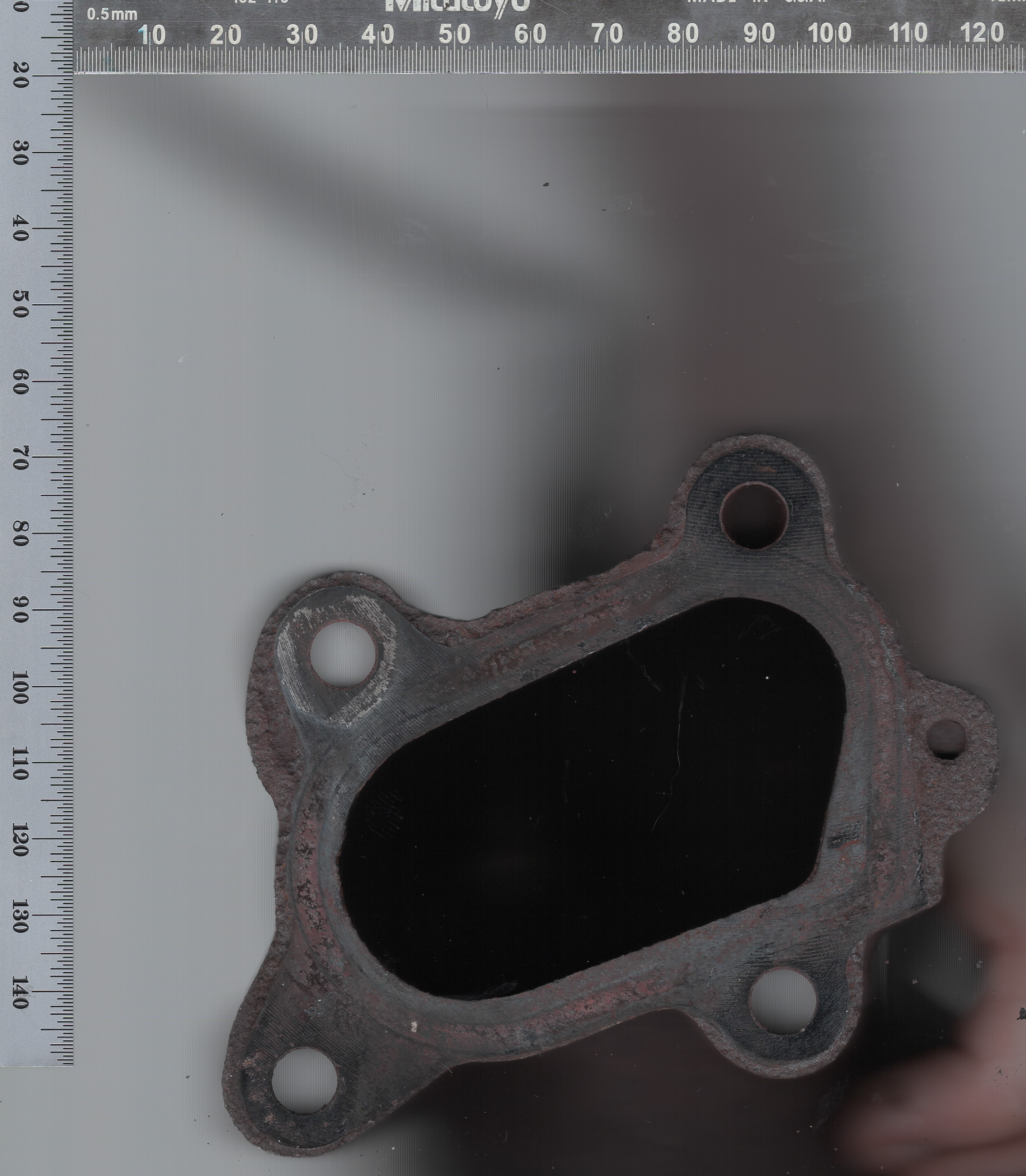
Since we are not making a mating part to this flange, care must be taken to model in the correct direction from the scanned image. This method of scanning and measuring provides very accurate measurements for flat parts.
Scanning arm
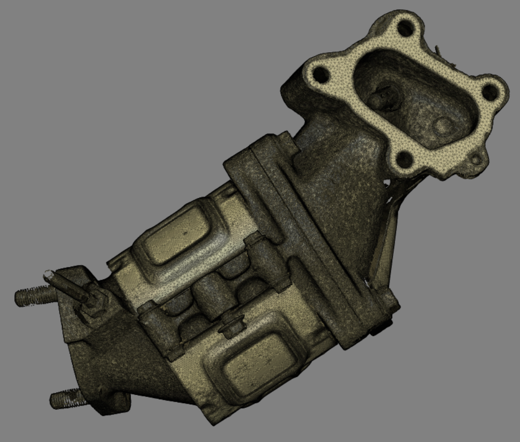
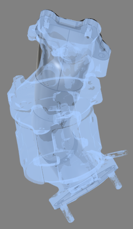
To produce the bounds of the OEM downpipe, it was scanned using a Romer arm. This produced a mesh which was exported as an STL and imported into AutoDesk Fusion 360.
Modeling
With the flat-bed images and the 3D scan in the same model, the flanges can be oriented in space with respect to the mesh.
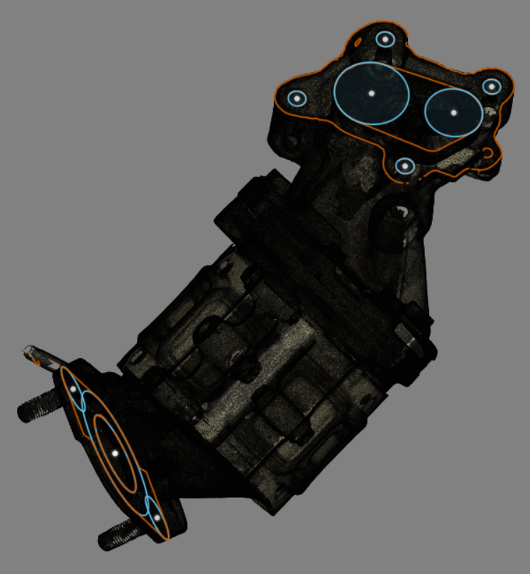
Three-dimensional features can then be modeled to connect the two flanges and checked that the new design fits within the bounds of the original part.
Turbine Outlet Elbow
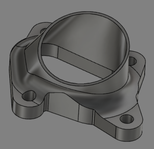
One of the most difficult aspects of this project has been modeling a turbine outlet elbow which flows and looks well, is manufacturable, and is economical. Several manufacturing methods could be used for making a part like this: sand casting, investment casting, laser powder bed fusion additive manufacturing, MIM post-processed additively manufactured green parts, 5 axis CNC machining, and 3 axis CNC machining.
Of those options, 3 axis CNC machining would be preferred, as it can be accomplished in-house. It is, however, the most difficult to make flow correctly and look good in this envelope.
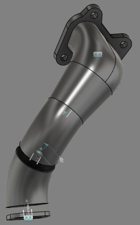
This part is going to be a weldment, so some standard bends were modeled and Fusion 360’s joint tools were used to orient them with respect to eachouther This allows the machined elbow and pieces of the weldment and individual joints to be manipulated with the other joints adjusting in real time.
Printing
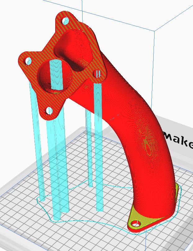
A fit test prototype was 3D printed using an Ultimaker 3 Extended using Proto-Pasta back-to-basics natural PLA. The extra Z height of the Ultimaker 3 Extended proved vital for printing this part in one piece.
Next steps
A 3D print can be used to check fitment and clearance. After the design is finalized the elbow will be machined and a welding fixture will be made. Then weldments will be produced and tested.